
1. In one sentence
Feedback control makes a robot repeatedly compare its intended state with sensor measurements and adjust its actuator commands to reduce the difference.
2. Why you need to understand it
A plan tells a robot where to go. It does not guarantee that the robot will arrive there. Motors have inertia, joints flex, loads change and objects push back. Wheels slip. Batteries and friction alter how the same command behaves. Even a precisely calculated trajectory can become inaccurate once hardware starts moving.
Feedback control is the layer that turns an intention into continuing physical correction. It operates inside robot arms, mobile bases, drones, grippers and legged machines. When a robot holds a pose, follows a path, balances or maintains contact force, a controller is comparing a target with measurements and deciding what the actuators should do next.
This is essential vocabulary for reading robotics news. A new AI model may choose a task or produce a motion target, but lower-level controllers still have to execute that decision on real hardware. “The model commanded it” and “the robot reliably did it” are different claims.
3. The core idea
A controller begins with a setpoint: the desired position, velocity, force or other measurable state. Sensors report the current state. The difference between desired and measured values is called the error. The controller applies a rule—called a control law—to turn that error into a command for motors or other actuators.
The new movement changes the robot, so sensors measure again. This repeated path from target to command to physical response to measurement is a closed loop. Northwestern University’s Modern Robotics materials describe robot controllers as continuously reading encoders, force sensors, vision or depth sensors and updating actuator commands to achieve desired behavior.
Different tasks require different objectives. Motion control regulates position or movement along a trajectory. Force control regulates how strongly a robot pushes on an object or environment. Hybrid motion–force control regulates motion in some directions and force in others. Writing on a board is a standard explanatory example: the tool follows a path across the surface while maintaining pressure into it.
The controller must be tuned. Corrections that are too weak can leave persistent error or make the robot respond slowly. Corrections that are too aggressive can overshoot, vibrate or become unstable. Stability means that errors remain bounded and tend toward acceptable behavior instead of growing into uncontrolled motion.
4. How it works
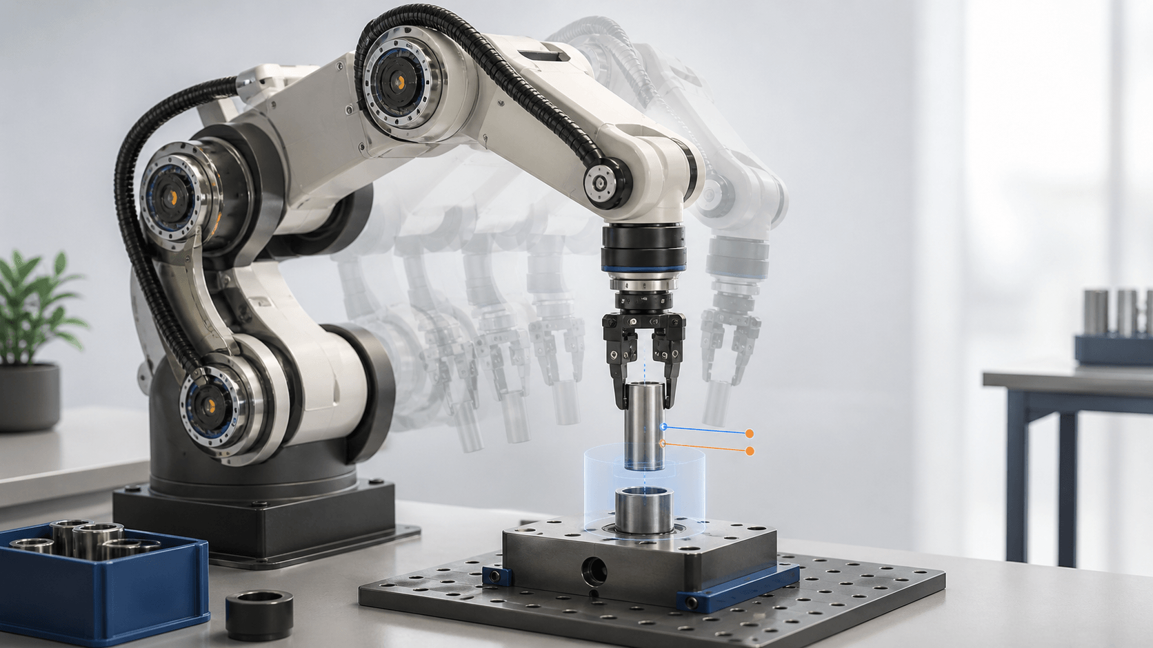
Consider a robot arm inserting a smooth cylindrical part into a matching fixture.
- Set the target. Planning provides a desired approach pose and insertion direction. The controller receives target joint positions, tool motion or contact force.
- Measure the current state. Joint encoders report angles, while motor-current estimates or a force–torque sensor can report interaction forces at the tool.
- Calculate error. The controller compares the target with the measurements. If the tool is left of the target, position error remains; if contact force is too high, force error has the opposite sign.
- Command the actuators. The control law requests motor torque, velocity or position changes. Drives turn those low-power requests into electrical current and mechanical force.
- Measure and correct again. The controller repeats the cycle. If the part contacts the fixture off-center, force feedback can reduce forward motion or permit a compliant adjustment rather than continuing blindly.
Real robots can contain several nested loops. A high-level controller may update the desired tool motion, while faster joint or motor loops regulate torque or current. Modern Robotics notes that arm controllers may evaluate commands roughly a thousand times per second, while inner amplifier loops can run tens of thousands of times per second; these are illustrative rates, not universal specifications.
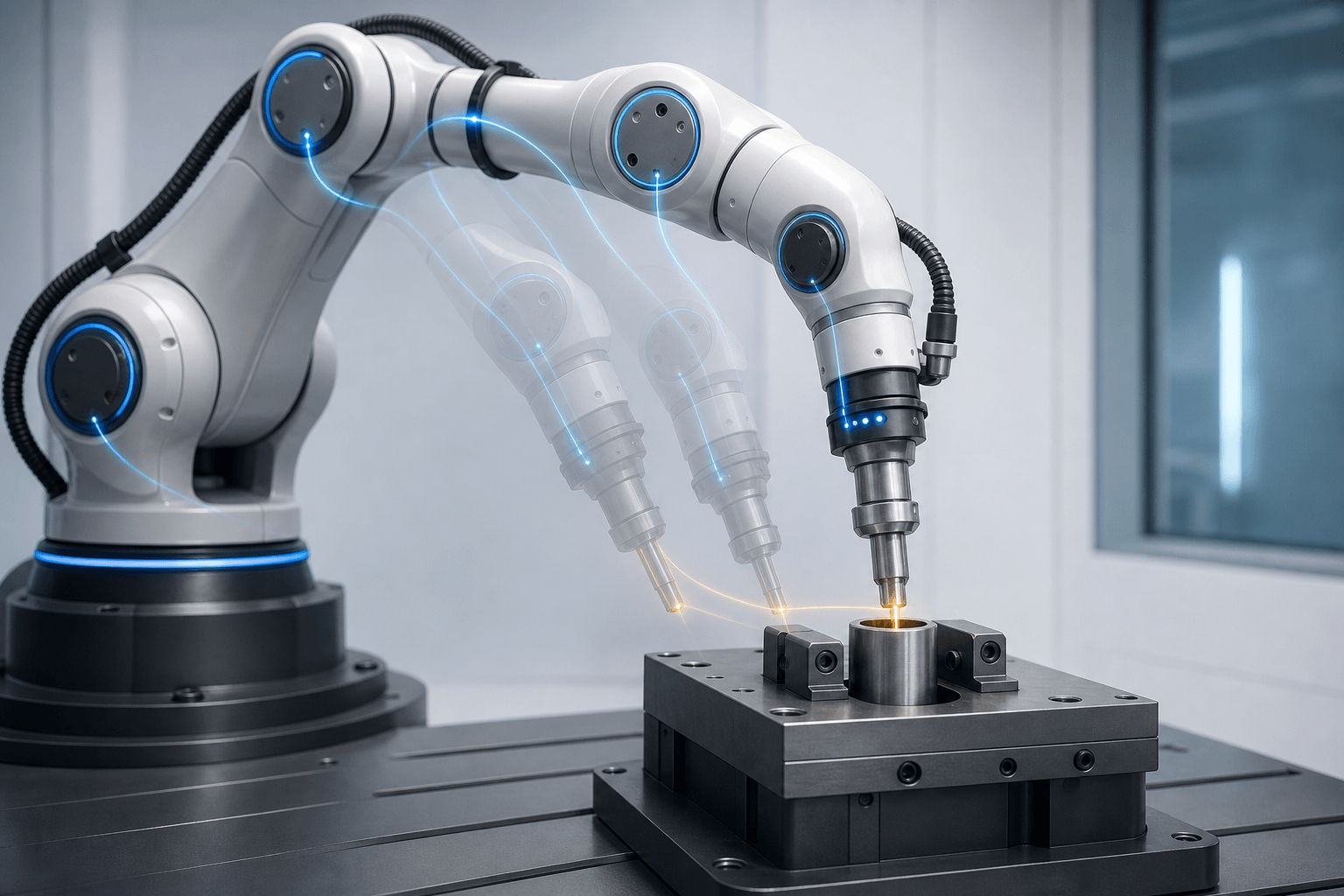
The controller repeats a target–measurement–correction cycle as contact changes the task. AI-generated illustration (not a photograph or measured data).
5. A real-world example
Universal Robots force mode — Commercial product feature. Universal Robots documents a force mode for its robot software and ROS 2 driver. In this mode, a user specifies a task frame, desired forces and torques, and which axes should be compliant. A compliant axis is one in which the robot can adjust its position to pursue the requested force; other axes can remain under position control.
This is a practical form of hybrid control. Imagine a tool moving horizontally across a surface while maintaining downward pressure. Position control directs travel along the surface, while force control adjusts vertical motion as the surface height changes. The official documentation states that actual applied force may be lower than requested because of joint safety limits. It also advises zeroing the relative force–torque sensor before use and warns that high acceleration can reduce force-control accuracy.
The documentation establishes that force mode exists as a commercial software capability and explains its interface. It does not prove that every application will be accurate or safe. Tool geometry, payload, mounting, process forces, speed, environment and risk assessment still determine whether a particular deployment works. Performance descriptions here are based on manufacturer documentation, not independent application testing.
6. Common misunderstandings
“A good plan guarantees accurate movement”
A planner can calculate a collision-free trajectory under a model, but the controller must execute it amid friction, load changes, disturbances and measurement error. Planning decides a desired course; control continuously manages physical deviation from it.
“AI replaces the control loop”
A learned model can produce actions, tune targets or even participate directly in control. Hardware still needs bounded, timely commands and measured responses. Many systems combine learned components with conventional controllers because fast correction, safety limits and predictable behavior remain necessary.
“Faster and stronger correction is always better”
High correction gain can make a robot react quickly, but delay, flexible structures and noisy measurements can cause overshoot or oscillation. Tuning is a trade-off among responsiveness, accuracy, smoothness and stability.
“Force control means the robot applies exactly the requested force”
Sensors have noise and bias, the tool and environment deform, and safety or actuator limits can cap the output. A requested value is a control objective, not a guarantee about every instant of contact.
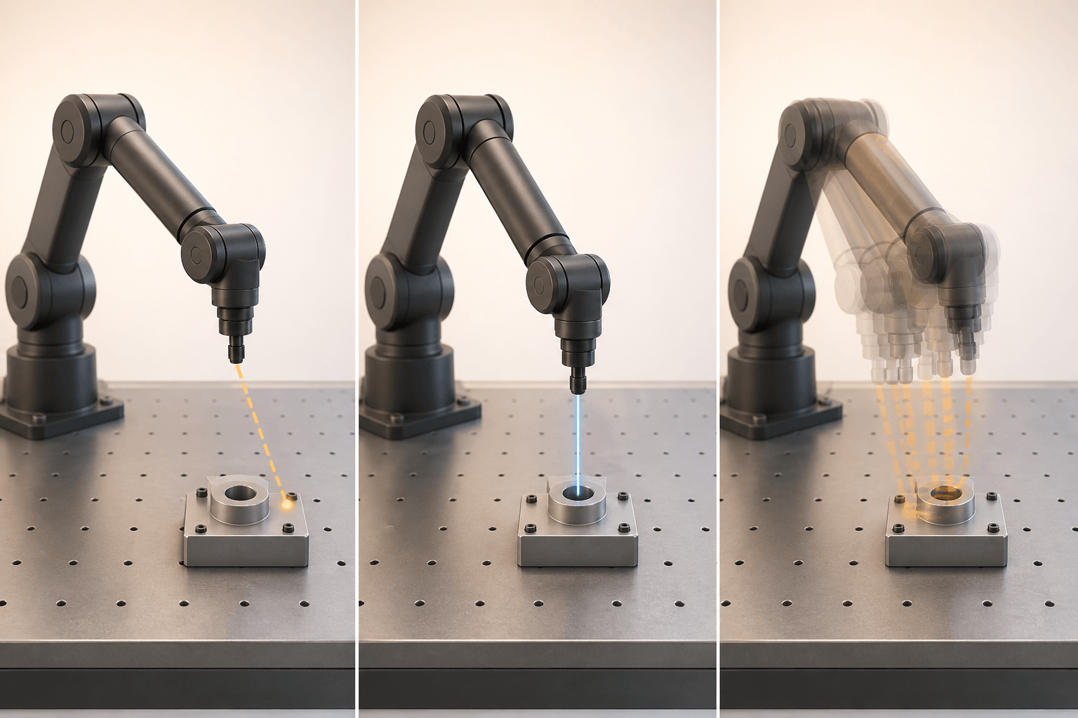
Correction must be responsive without becoming unstable; more aggressive feedback is not automatically better. AI-generated illustration (not a photograph or measured data).
7. Current limitations
Feedback is only as useful as its measurements. Encoders can be precise while still missing flex elsewhere in the mechanism. Force sensors can drift or include loads caused by the tool itself. Cameras introduce processing delay. When the measured state differs from the physically relevant state, the controller can confidently correct the wrong error.
Actuators also have limits. Motors cannot deliver unlimited torque or change speed instantly. Commands may saturate at a hardware or safety boundary, so the controller’s requested correction is not fully executed. Backlash, friction, flexible links and soft objects make the robot’s response harder to model.
Time matters. Measurement, computation, communication and actuation all add delay. A correction based on old information can arrive after the system has already changed. Faster loops help only when sensors, computation and hardware support them; raising the update rate does not remove poor models or noisy data.
Contact tasks are especially difficult because the environment becomes part of the controlled system. A rigid metal fixture, a sponge and a human arm respond differently to the same movement. Controllers must be designed and tested for the actual task, and safety cannot be inferred from intelligence or compliance alone.
8. Key takeaways
- Feedback control repeatedly compares a target with measurements and commands corrections.
- Planning selects desired behavior; control manages how real hardware follows it.
- Motion, force and hybrid control serve different physical objectives.
- Stronger or faster correction can cause overshoot and instability when tuning, delay or sensing is poor.
- Commercial control features still require application-specific setup, limits and safety engineering.
9. Where to go next
This is article 4 of the six-part Beginner guide path. Read What Makes a Machine a Robot?, What Is Embodied AI—and Why Does a Body Change the Problem? and How Robots Sense the World—and Why Sensing Is Not Understanding first. Continue with How Robots Learn From Human Demonstrations, followed by What Robot Autonomy Really Means as those guides are published.
10. Sources & evidence
- Control System Overview — Modern Robotics, Northwestern University.
- Chapter 11: Robot Control — Modern Robotics, Northwestern University.
- Robotic Manipulation — MIT OpenCourseWare.
- Universal Robots Script Manual: force_mode — manufacturer technical documentation.
- Force and Torque Control — Universal Robots ROS 2 Driver documentation.
Sources — How Feedback Control Turns Robot Commands Into Reliable Motion
Access date: September 2, 2026
1. Control System Overview
- Authors: Kevin M. Lynch and Frank C. Park
- Institution: Northwestern University, Modern Robotics
- URL: https://modernrobotics.northwestern.edu/nu-gm-book-resource/11-1-control-system-overview/
- Publication date: Chapter resource; page does not state a separate date
- Source type: University textbook supplement
- Supports: Closed-loop control, controller–actuator–sensor relationship, motion and force objectives, nested control loops and illustrative update rates.
2. Chapter 11: Robot Control
- Authors: Kevin M. Lynch and Frank C. Park
- Institution: Northwestern University, Modern Robotics
- URL: https://modernrobotics.northwestern.edu/chapters/chapter11/
- Publication date: May 22, 2018 for the chapter playlist
- Source type: University textbook supplement
- Supports: Error response, motion control, force control and hybrid motion–force control.
3. Robotic Manipulation
- Instructor: Professor Russell Tedrake
- Institution: MIT OpenCourseWare
- URL: https://ocw.mit.edu/courses/6-4210-robotic-manipulation-fall-2022/
- Publication date: Fall 2022 course
- Source type: University course material
- Supports: Relationship among perception, planning, dynamics and control in autonomous manipulation.
4. Universal Robots Script Manual: force_mode
- Institution: Universal Robots
- URL: https://docs.universal-robots.com/PolyScopeX_SDK_Documentation/build/SDK-v0.18/_static/pdf/scriptManualG5.pdf
- Publication date: SDK documentation; separate date not stated on source page
- Source type: Manufacturer technical documentation
- Supports: Force-mode parameters, compliant axes, requested wrench, speed/deviation limits and safety-limit boundary.
5. Force and Torque Control
- Institution: Universal Robots
- URL: https://docs.universal-robots.com/Universal_Robots_ROS_Documentation/rolling/doc/ur_robot_driver/ur_robot_driver/doc/usage/force_torque_control.html
- Publication date: Continuously updated technical documentation
- Source type: Manufacturer technical documentation
- Supports: Joint torque control, Cartesian force mode, combination with position control, force–torque sensor use and sensor-zeroing guidance.
- Attribution boundary: The documentation establishes the commercial feature and interface, not independent application performance.